Brake Upgrades Master Cylinder Edition

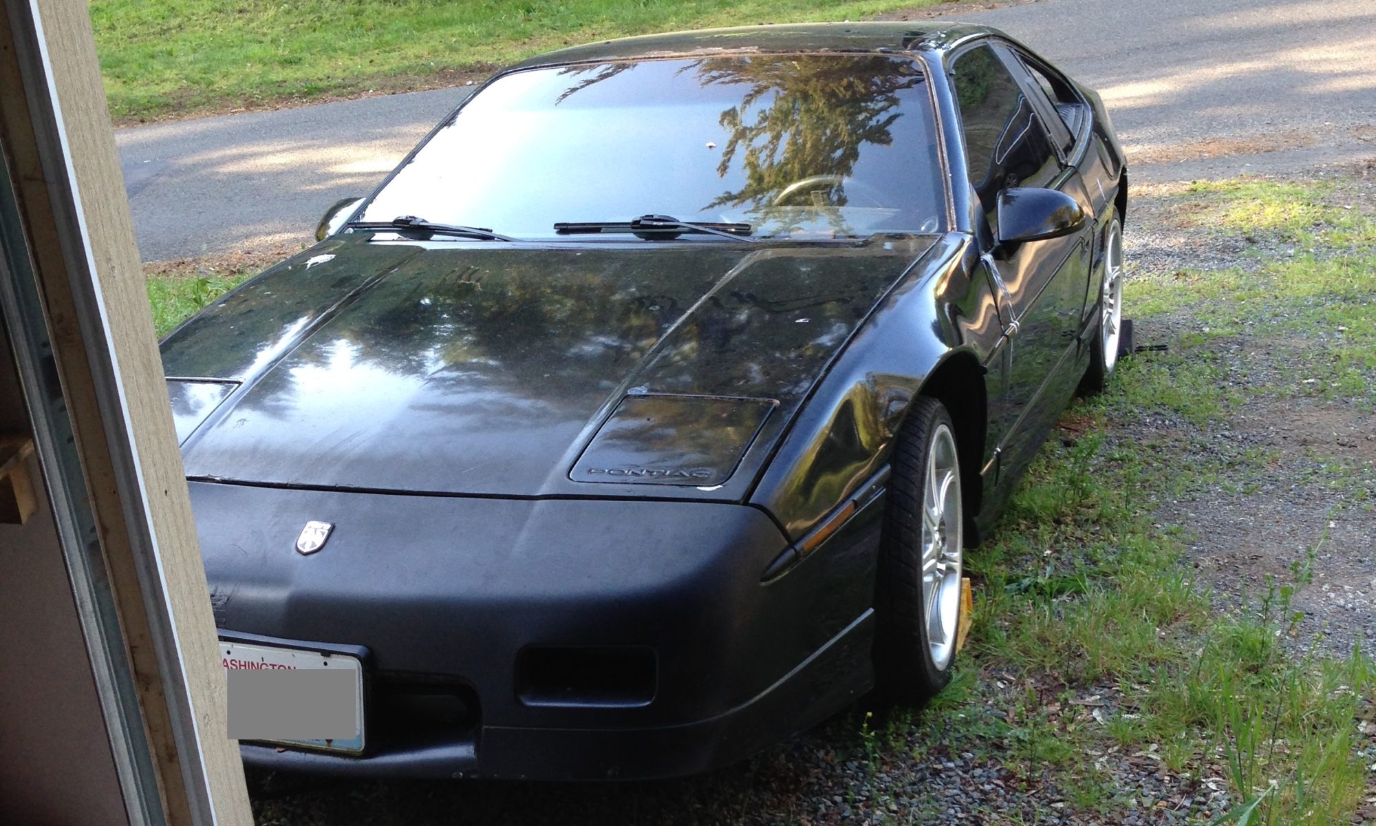
I’m doing a light brake upgrade on the Fiero (http://myfiero.oceanmoon.com/how-to/brakes/the-easiest-fiero-brake-upgrade)

When I went looking for the “94 Blazer master cylinder” mentioned in the article I found two different bores listed and then fell down a rabbit hole of master cylinder research….

Seems like people use one of four master cylinders for the pre-’87 Fiero:

  • Stock ’87 Fiero :  1″ (stepped from 1.417″)
  • Full size blazer:  apparently 1-1/8″ and 1-1/4″ versions are available (no step data found)
  • S-10 blazer:  15/16″ (stepped from 1-7/16″)

There is very little information available on whether folks are using the 1-1/8 or 1-1/4 full size blazer master cylinder.

Trying to get exact bore sizes of MCs from the various web sites is difficult.  Most master cylinders are “stepped”–that is, they have two different bore sizes.  Usually a larger piston that is actuated first and moves lots of fluid quickly at low pressure to “take up the slack” in the system, then the smaller piston to really drive the pressure up (smaller piston means more pressure for a given pedal travel).

Information on stepping and bore sizes doesn’t seem to be great or consistent.  For example, part # 10-2352 on the O’Reilly website lists a ’94 full size blazer MC, with an imperial bore size of 1.125 inches,  and a bore size in metric of 40 mm (that’s 1.57″ inches).  Clearly they are conflating the stepped bore sizes.

From what I can see on most parts websites, the given bore for an MC is usually the primary (smaller) piston.

This larger bore size for initial pedal travel may explain why people seem to have different preferences.  I could imagine that, depending on whether all the wheel calipers have been upgraded, and the relationship between the stepped bore sizes, the overall brake pedal feel could vary quite a bit.

I put together a Google spreadsheet that attempts to make quantitative sense of the varying master cylinder and caliper combinations.  Note these calculations are not verified and I dropped out of the Physics program (yes, really).  No warranties are expressed or implied and you should run your own numbers before making changes to your braking system.

Fiero MC Google Spreadsheet

Following is some stream of consciousness discussion trying to make sense of a few things.  Read at your own risk.

Beretta calipers with stock MC

We can say for sure that with Beretta calipers on the front (larger pistons than stock calipers), the pedal travel will be increased over the stock braking system (more fluid to move).

We can also say that the force the pistons exert on the brake pads will be higher than in the stock system for the same distance of pedal travel once you’ve moved into the smaller bore part of the MC stroke (more surface area on the caliper piston for the pressure to act on).  But remember these MCs are stepped, and the “big part” of the piston in the Fiero MC is meant for smaller calipers.  So you’re probably engaging the “high pressure” part of the stroke sooner than you would with the stock MC (or than you would with the Beretta calipers in a Beretta).  I’m not sure what the real world effects of this would be.

Other Thoughts

The beretta rotors are the same diameter as the Fiero rotors, and the pads have slightly more surface area than the OEM Fiero pads.  So for similar stopping performance you would want similar or slightly lower pressures on the pads (I would think).

’94 blazers use drum brakes on the rear so there may be some residual pressure valve (RPV) considerations.

Recommendations

The full size blazer MC seems like the best choice going purely by the numbers.  For either bore size it produces pressures at the brake pads within +/- 15% of those produced by the stock MC, and the larger bore size should help move the extra fluid required for the larger calipers without excessive pedal travel.


Brake Upgrades Part One

I’m doing a light brake upgrade on the Fiero per http://myfiero.oceanmoon.com/how-to/brakes/the-easiest-fiero-brake-upgrade

This is a nearly bolt-on upgrade and involves using a caliper from an early 90s Beretta/Grand AM and some modifications to the OEM rotor/hub (pre-’87 Fieros have the wheel hub and brake rotor as a single casting).

I’ve taken some photos of the machining I did on the rotors.  All work was done using a lathe.

For this rotor I had access to a large lathe so I grabbed the assembly by the rotor and used a parting tool to remove the inner hub from the rotor.  There are other ways you would go about this on a smaller lathe (holding the part would probably be different, and possibly a different operation to separate the parts).

This picture is the rotor still in chuck after removing the inner hub.

Here is the inner hub right after separating it from the rotor above.

I used the smaller lathe in my shop to turn down the diameter of the inner hub to fit inside the Beretta/Grand AM rotors.

Here is the original hub after being turned down to the appropriate diameter.  I also decided to face a few thousandths off the outer mating surface to clean up all the rust and old paint and make sure it was perpendicular to the spinning axis.  It also makes it nice and shiny…

Here’s the original hub being set inside the new rotor.

Original hub fully seated in new rotor.  I had about 0.005″ clearance.  We’ll see if I regret that after a couple years of rust and racing…

New hub installed on the car, without wheel studs or the new rotors.

Preliminary testing indicates that facing off the outer mating surface just a few thousandths moved the rotor close enough to the heat shield that the rotor just barely rubs on the shield.  So I guess some tweaking will be required there…

Fiero Lower Ball Joint Replacement

This job turned out to be more work than I thought.  Getting the joint out was easy enough with a hammer and a big socket.

For installation I got a hold of a ball joint press from O’Reilly’s tool loan program.  Unfortunately it’s not really meant for tiny little control arms like the Fiero has.

I found some info on using the generic press on a Fiero, but no close-up pictures or good explanations (this post has close-up pictures, and I hope a good explanation).  Here is what I ended up doing.  You need:

-Ball joint press.  I had the generic “evertough” brand one from the O’Reilly tool loan program.  No special adapters–just three spacers and an “anvil” for each end of the tool.

-Piece of 1/4″ steel plate, about 2×3″.  The critical dimension is it can’t really be wider than 2″.

-A BIG flat washer.  The one I used was 2″ OD and  13/16″ ID.  Anything bigger than the base of the ball joint with an appropriate hole for the zerk fitting boss in the middle will work.  You could also drill the appropriate size hole in your steel plate and forgo the washer.

Use the appropriate size spacer from the press kit (the generic steel rings) and anvil on the open side of the press.  In my kit, the right adapter was the smallest ring.  This side will go over the threaded end of the ball joint.

The remaining anvil is meant to go on the threaded side of the press but it’s too big and will hit the control arm before it presses the joint in.  Instead, use some tape and stick the big washer to the middle of your piece of steel.  Put the middle of the washer over the threaded boss for the zerk fitting in the middle of the ball joint.  This is your new anvil–the washer makes sure you press on the edges of the ball joint (the boss in the middle is raised just above the edges and you don’t want to squish it).  Tighten the press onto your new anvil.  This is a lot of fun trying to hold everything together and lined up.

Here’s the “anvil” I used for the base of the ball joint.  The washer is just stuck on with painter’s tape:


This is the setup for pressing it in:

Here is the DIY anvil from the backside:

Here you can see the washer in between the steel plate and the ball joint.  You want the hole lined up with the zerk fitting boss.

I couldn’t get the joint to go in completely straight, but this setup left me enough wiggle room I could move the threaded part around on the steel plate closer to a high side and straighten it out.

Installing Flywheel Ring Gear–Oven Method

See, we had to build the racecar at my house because I’m not married so I’m allowed to use the oven for car parts:

Baking flywheel ring gear in kitchen oven at 350 degrees

The trick of baking the ring gear in the oven at 350 degrees worked like a charm.  It dropped right onto the flywheel.

I thoroughly cleaned the flywheel edge and inside of the ring gear using a green scotch-brite pad and brake cleaner before putting the gear back on.  You especially want to make sure the ring gear doesn’t have any junk on it because it will smoke/stink up your house in the oven.

I put the flywheel on the kitchen floor right next to the oven and on top of an old piece of wood (to protect the floor).  Once the ring was heated through (10 minutes or so) I grabbed the ring with pot holders and went from the oven directly to the flywheel within a second or two.  Piece of cake.

I removed it using a hammer and punch–just went gently around the perimeter and it was off in a couple of minutes.


Flywheel Machining

Swapping a 3800 into a fiero requires a flywheel that will fit on the engine and not interfere with the transmission.  There are a few ways to go about this but generally the simplest is to use a modified 3800 flywheel.  These can be purchased or made from a flywheel for vin K Camaros from the early 2000s.  When I bought the car, it came with a brand new Camaro flywheel so I decided to work with that.

Side note:  The stock Camaro flywheel has several dowel pins around the perimeter that mate with the stock Camaro pressure plate.  These need to be removed to work with the Fiero and before any machine work can be done.  I had a really hard time grabbing them, and what finally worked was to thread a die onto them and use that to twist and grab them.  The right size die was one a little too small–you want it to thread onto the taper at the beginning and then stop and grab.  Once the die grabs you can twist (clockwise only) while pulling away from the flywheel and they should come out pretty easily.

Back to machining:  Shops in Seattle didn’t seem interested in doing this job and couldn’t give me reliable estimates on the cost.  As of this writing West Coast Fiero sells a pre-made flywheel for $295 which is probably at least what machine work will cost in a big city.

I have access to some facilities and expertise so I finally buckled down and removed 0.270″ of material from the friction surface of the flywheel using a large lathe.  I measured the runout before I started working on it and it was about .004″.  I removed the ring gear and mounted the flywheel in a 4-jaw chuck.  I centered it in the check and then used a dial indicator to make sure the friction surface was running true to the cutting tool.  Then I did a series of facing operations until the right amount of material was removed.

The finished thickness from the crank mounting surface to the friction surface is supposed to be 0.840″.  I ended up with .830″ so I messed up somewhere.  But there is some wiggle room here so it will be fine.

I’ve never machined cast iron before so that was interesting.  Lots of messy chips.

The most interesting thing with the job was once I was deeper into the flywheel I exposed a number of casting flaws (pictures below.  It’s not to clear to me if they will affect the clutch performance noticeably or affect strength.  We’ll find out.  For what it’s worth, this flywheel was made by AMS Automotive.

casting flaws between 4 and 7 o’clock.
Close up of casting flaws in flywheel

The flywheel needs to be rebalanced next.  I’ll cover that in another post.

Now that I’m about done with this part I have a much better idea of the quality of the flywheel casting and the machining costs.  Based on this information, if this wasn’t a Lemons car ($500 limit) and I hadn’t gotten the Camaro flywheel with the car, I would absolutely buy a pre-modified flywheel.  With the variability in flywheel quality and machining costs, there is zero risk-adjusted savings in modifying a flywheel.


Hose Specs Matter

Swollen fuel line from hose not rated for gasoline immersion being used inside a fuel tank

The new engine in the racecar requires more fuel volume than the original so I replaced the fuel pump.  The Fiero uses an in-tank fuel injection pump.  The above picture is the old pump when I took it out.  See the hose is swollen around the clamps?  It was very soft inside and out.  The writing on the side said it was rated for 50psi.  So this was probably either SAE 30R7 or 30R14 hose–neither of which are rated for fuel injection pressures or for immersion in gasoline (most fuel line is only intended to handle gasoline on the inside).

SAE30R10 is rated for fuel injection pressures and immersion in gasoline.  That’s the right stuff to use here.  My replacement pump came with a little piece of it.

Intro — Building a racecar from a 1987 Fiero

I started building this “racecar” in April 2016.  I’ve been learning some interesting stuff along the way so I’m starting a blog to share.

I’m using the term racecar loosely.  The idea is to use this as a cheap track car and/or enter it the Chump or Lemons races.  Both of these races have a dollar limit of $500 (excluding safety equipment) which sometimes requires some creative work for cost savings.

The car is a 1987 Pontiac Fiero GT.  I bought it from a guy who had started to swap in a GM 3800 Series II engine (from a circa 1999 Oldsmobile Eighty-Eight).  He was in way over his head so I bought the car and a truck full of parts.  The project so far has involved the actual conversion work plus undoing a lot of the previous owner’s efforts.  The one thing I will say for the former owner is he did collect almost all the parts and sold them with the car.